Resources
- We provide a set of online tools to instantly quote Rapid Prototyping & Manufacturing Services models. If you need a quote for fast turn “strip and ship” parts or an quote for a show model with custom graphics LaserSintering.com has the tools to help you out.
To get a instant quote all you need is:
- A STL File exported from any CAD software (click here for exporting tips)
- Click on the “START A NEW QUOTE” button on the main page of your account
- To add files simply press the “BROWSE” button and select the file location
tip: for faster upload ZIP your STL files together
- After the upload is complete adjust the quantity, select the material and finish to complete the quote.
- Click the “ORDER” Button or save your quote and return to it within 30 Days
- Registration
- File Upload
- Order Parts
- Saved Quotes
- Manual Quotes
- Account Information
- What to Expect
- Lead Time
- Credit Terms
Registration
Registration is fast, free and easy. You can sign up on the main page by using the “Register” button or “START A NEW QUOTE” link. We only require basic information be filled out to start using our free quoting service
File Upload and Security
The concept of the Online Quoting and file handling is that no persons have to look at the files in order for the client to obtain pricing! There are literally thousands of quotes provided every year without any persons seeing the files other than the client. This is part of one of our protections of you data. This saves time and cuts the cost to run our business at the same time greatly increasing the security.
Order your Parts
Ordering parts with us is fast as easy. Once your quote has been completed you can click the “ORDER PARTS” button to continue. Now you can enter your payment and shipping information if it differs from your default settings. Next you verify your order and submit to LaserSintering.com via a secure 128-bit encrypted transfer.
A project manager will follow up with you shortly after to provide shipping information. Additionally if you would like to inquire about credit terms you can speak with your project manager or click here.
Retrieving Saved Quote
Quotes can be saved and remain valid for a period of 30 days. You should save a quote if you need to get approval or plan on ordering at a later date. All files associated with the quote will also be saved for 30 days but will be automatically removed after 90 days.
Submitting a Manual Quote
If your project is complex, uses multiple materials, or requires additional finishing such as paint or graphics a project manager can then view the quotation and the special request. To submit the Manual RFQ simply click the”REQUEST A MANUAL QUOTE” button on the bottom of the page. Your project manager has the ability to adjust pricing for the manual quote. They will work with to get you a price and lead time for you special request.
With in 4-8 hours you will receive this updated quote via e-mail. This quote will be saved under your user account where you can access it for up to 30 days and order parts.
Changing Account Information
You can update user account information at any time. Simply log into your account and click the “ACCOUNT INFO” button to access all your existing account information.
What to Expect from LaserSintering.com
Upon placing an order using the online ordering system you can expect three emails form LaserSintering.com.
First, you’ll receive an e-mail confirming that your order has been placed and let you know that your project manager will follow up with you when he receives the order and gets it scheduled.
Second, your project manager will contact you confirming the delivery date and informing you that everything is good with the file and the part is in queue and ready to be grown.
Third, will be the tracking number of your project alerting you that it has been shipped.
Typical Lead Time
Leads times will vary greatly from job to job. However we strive to provide the fastest turn around times for our customers at no extra charges. Parts that are under 12 ” x145″ x12″ and less then quantity of 2 will typically ship within 24hrs of placement of the order. Larger parts or higher quantities typically take 4 days. Lead time very rarely go beyond 6-8 days.
Lead times for additional service such as urethane castings vary greatly but carry a 1 week minimum. If you have any additional request please contact your project manager and they will be happy to assist you or click here for our different delivery time options
Applying for Credit Terms
If your company would like to be considered for credit terms please click here to download the Credit Application . Please fill out the application to the best of your ability and submit it Via Fax to 512-524-3638 . Approval typically takes from 24 to 48 hours.
- Below are some useful links that can serve as a guide to help you design your parts for rapid prototyping. There are only a few basic guide lines to follow to achieve the best possible part file that you can. If you have any question if your part will grow or not please ask your project manager and they will be able to answer any question you may have.
Living Hinge
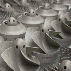
Most SLS materials work very well for parts with living hinges and snap features, including Duraform GF, EX and Nylon 12/PA. There are also a small handful of cast urethane materials which work well.
Minimum Feature Size
SLS
The minimum feature size for SLS parts is typically .020”. Minimum recommended wall thickness is .030”. Part orientation can help certain features be produced more successfully. It is important to advise us if there are any critical dimensions that need to be achieved.
DMLS
Parts at built at such fine layers, fine features and tight tolerances are much more achievable with this technology. Certain geometries can meet tolerances as tight as .002” while others may only be achievable to .008”. The minimum wall thickness recommended can be as low as 0.010″, but some walls need 0.020″
Part orientation is also in significant in helping features and tolerances being met.
Hollow Parts
Creating a hollow part is a good technique to use to cut down on the volume of the prototype. This is important because volume is one of the main factors that play into the price of the prototype. A part with a lower volume can be created quickly and more cost effectively.
Faceting & Stair stepping
Stair stepping on parts built using DMLS is hardly visible but does exist. In general, surface quality of DMLS parts is very fine and requires very little post finishing.
This occurs because the model is grown in layers. If the layers are further apart (.010″) you will notice heavier stepping on your parts. If the layers are closer together (.006″) then the stair stepping will be reduced and not be as noticeable.
Another factor that effects the surface finish of the SLS model is Faceting. This is controlled by the output settings on your 3D CAD software. If you export a coarse setting the part will appear to have many triangles over the surface Coarse Image, however if you export a part with fine faceting the file may be to large and unmanageable Fine Image . The key is to fine the balance that will take into consideration features and part size to give you the best possible file.
Text & Logos
Text and logos follow the same rules as small features do. If your text and/or logo is a important part of the prototype please let your project manager know. The reason is that some times the best orientation for the part to grow is not the best for the logo. When possible keep spacing between letter around .020″ and try to use common fonts such as “arial” “tahoma” or “veranda” because these are design to print clearly even at smaller sizes.
-
Overview
Generating STL files is usually a fairly simple process. Virtually all modern CAD systems now include STL output as a standard feature and, for the most part, the files created are suitable for rapid prototyping. But the extra step of converting CAD models into STL format still presents a barrier to Rapid Prototyping & Manufacturing Services novices or occasional users. Imagine how annoying it would be if you had to select parameters and convert word-processing documents or spreadsheets into a special file format before you could print them.
Making STL files is further complicated by the fact that every CAD system uses different terms and parameters for defining the STL file’s resolution, requiring users to interpret such mystifying terms as chord height, absolute facet deviation, angle control, and adjacency tolerance.
Such terms are needlessly confusing. The STL file format is simple. It’s not necessary to understand precisely what all the CAD system parameters mean in order to create useful files.
An STL file is simply a mesh of triangles wrapped around a CAD model. CAD system settings specify how closely the STL mesh conforms to the actual surface geometry of a part. A mesh with triangles that are too large will create a small STL file, but the prototype made from it will have visible facets. A mesh with triangles approximately the size of the layers used by the Rapid Prototyping & Manufacturing Services systems (typically about 0.003 inches or 0.075 mm) will produce a prototype with the best fidelity. A mesh with even smaller triangles will increase the size of the STL file and take longer to process, but it won’t increase prototype accuracy or resolution.
Coarse Mesh
Fine Mesh
If an STL file is set with too loose a tolerance, facets will show on the prototype (left). Ideally, the triangle size should be close to the layer thickness used by the Rapid Prototyping system.
It would make sense for the Rapid Prototyping machine manufacturers to work with the CAD software folks to develop a set of standard drivers that would eliminate the need for users to select STL output parameters. Whenever the idea has been suggested to 3D Systems or Stratasys, however, executives have brushed it off, saying they will get around to it sooner or later.
Service-bureau recommendations:
We have surveyed rapid prototyping services and find that they generally agree on the STL settings for various CAD systems that will produce the best rapid prototypes. Regardless of the parameters that any CAD system uses to define model resolution, service bureaus say the chord height of an STL file (the maximum distance a point on a triangle can deviate from the true surface of the part) should be between 0.001 and 0.003 inches (0.025 and 0.075 mm). Whenever possible, STL files should be in binary format. (In the past, some CAD systems did such a poor job of STL creation that developers included an ASCII STL option as a debugging tool. ASCII STL files tend to be huge, but they can be edited with a text editor.)
Some CAD systems will generate error messages during STL conversion saying that some part geometry is outside of the positive X, Y, Z quadrant or is in negative space. These messages can be ignored, as the STL file will be located in the Rapid Prototyping machine’s build space and oriented for optimal surface finish and build speed by the system software.
If you’re using a solid-modeling CAD system listed below, the following settings should produce good STL files. If you’re using a surface modeler or another system not listed, we’d suggest discussing file preparation with your service provider or in-house prototyping shop. Surface-modeling CAD systems describe part geometry using mathematical patches with no thickness. In order to create good STL files, all of these surfaces must be joined so that there are no gaps or overlaps. This stitching or sewing, as it is frequently called, can be a tedious process, and it’s easy to miss small flaws that can crash a Rapid Prototyping system.
SolidWorks
- Open your model and from the File menu choose Save As.
- Set the file type to STL.
- Click on the Options button at the bottom of the Save dialog box.
- Select Output as Binary and select the desired units (inches or millimeters).
- Set Quality to Fine.
- If you want to preview the STL model before saving, check the “Show STL info before saving” box
- Name and Save your STL file.
STL files can be created from SolidWorks parts or assemblies. If you wish to create an STL file of an assembly, there is a check box at the bottom of the Export options dialog box to save the assembly as one STL file or individual STL files for each part.
SolidWorks also allows users to use custom triangle deviation settings. With our test file, using SolidWork’s coarse settings resulted in a 244-kilobyte STL file with visible facets. The default fine settings (triangle deviation 0.006 inches) produced a smooth file of 836 kilobytes. Setting a custom deviation of 0.003 inches made an 1,828-kilobyte file. An ASCII STL file generated with the fine settings was 7,894 kilobytes.
Pro/Engineer
- Open your model and from the File menu choose Export/Model.
- Select the file type STL.
- In the Export STL dialog box, set Format to Binary.
- Set the Chord Height to 0. The field will be replaced by a minimum acceptable value for the geometry of the model.
- Set Angle Control to 1.
- Name the file and click the OK button. Pro/Engineer will save your STL file.
SDRC I-DEAS
- From the File menu, select Export/Rapid Prototype File.
- Select the file to be exported.
- Select Prototype Device to SLA500.dat.
- Set Part Positioning to Centered.
- Set Absolute Facet Deviation to 0.000395 inches.
- Select Binary as file type.
- Name and Save your STL file.
SolidEdge
- Open your model and from the File menu choose Save As.
- Select the file type STL.
- Click on the Options button in the Save As dialog box.
- Set the Conversion Tolerance to 0.001 inches or 0.0254 mm.
- Set the Surface Plane Angle to 45o.
- Select the Binary radio button and click the OK button.
- Name and Save your STL file.
Unigraphics
- Open your model and from the File menu choose Export/Rapid Prototyping.
- Set Output Type to Binary.
- Set Triangle Tolerance to 0.0025.
- Set Adjacency Tolerance to 0.12
- Set Auto Normal Gen to On
- Set Normal Display to Off.
- Set Triangle Display to On.
- Name and Save your STL file.
CATIA v4
- Select STL command
- Set Maximum Sag to 0.0005 inches or 0.0125 mm.
- Pick the model to be converted to STL.
- Select Yes to generate triangles.
- Select Export, type a file name, and click OK to output an STL file.
Note: CATIA has a utility for checking and analyzing STL files. It is a good practice to check the direction of normal vectors (they should point outward) and verify that the STL surface is closed. Parts created as CATIA solids should be no problem. Parts created as volumes from surfaces are more likely to have flaws.
